Introduction
To provide every item a common reference point, the International Organization for Standardization (ISO) established a framework into which the key network hardware and software components and protocols could be put. This framework, known as Open Systems Interconnection (OSI), is a seven-layer architecture that allows components and their functions to be linked as well as components and protocols to be standardised.
More information on ISO may be found at https://www.iso.org. Check out the real standards, such as ISO/IEC 7498-1:1994 and ISO/IEC 7498-2:1994 Open Systems Interconnection—Basic Reference Model in Information Technology: http://standards.iso.org/ittf/PubliclyAvailableStandards/index.html The Basic Model
The OSI model offers a crucial common language for network hardware and software engineers to interact and guarantee that their devices operate together. The model’s layers each reflect a different element of network function.
The CompTIA Network+ test requires you to know the layers’ names, how they interact with one another, and what they represent.
The OSI model aids in describing the connections between network protocols as well as standardising the architectural aspects of network components. To get your data into a network, you’ll need more than one protocol or action, as you’ll see.
What Do the OSI Layers Represent?
Physical Layer is the first layer
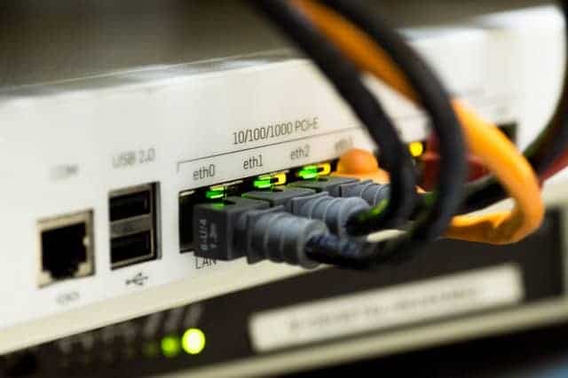
The Physical layer of the OSI model provides network standards for the electrical signals that pass through network cables, connections, and media types (cables) itself. The Physical layer also controls how data is distributed over network mediums.
You’ll need examples of components that run at each tier of the OSI model to pass the CompTIA Network+ test. Cables are one example of a network component that belongs in the Physical layer. The Physical layer is also used in wireless transmission. In their heyday, hubs functioned at this stratum.
SONET/SDH, Bluetooth, and Wi-Fi are examples of Layer 1 protocols.
Data Link Layer is the second layer
Layer 2, the Data Link layer, specifies the rules for assembling and finishing all of the pieces that make up a data frame before passing it to a Physical-layer device and into the network.
A network’s magic begins with the network interface card, or NIC (pronounced “nick”), which acts as the link between the PC and the network. NICs are available in a variety of forms and sizes. A network interface card (NIC) was a separate card that snapped into a convenient expansion slot on earlier computers, which is why they were named network interface cards. NICs are still named that even though they’re now integrated into the motherboard.
To ensure that data is sent to the correct system, the network must offer a method that assigns each system a unique identity, similar to a phone number. That is one of the most critical responsibilities of the NIC. Every NIC contains special software with a 48-bit identification known as the media access control address, or MAC address, which is written onto some sort of ROM chip.
There is never a time when two NICs have the same MAC address. Any NIC manufacturer must obtain a block of MAC addresses from the Institute of Electrical and Electronics Engineers (IEEE), which it subsequently burns into the ROM chips of its NICs. Many NIC manufacturers additionally print the MAC address on the NIC’s surface.
The MAC address is written as 12 hexadecimal digits, with each group of two separated by a dash, such as 00–40–05–60–7D–49. The first six numbers, in this case 00–40–05, are the NIC manufacturer’s number. No other manufacturer may use those six hex digits, known as the Organizationally Unique Identifier (OUI), once issued by the IEEE to a manufacturer.
Open a terminal or command line. Type ipconfig/all on a Windows system and look at the Physical Address value. Type ip a on a Linux machine and check for the value for link/ether. Type ifconfig on a Mac and check for the ether value. Between each two hex characters, Linux and Mac employ a colon, but Windows uses a dash.
So, every NIC on the planet has a unique MAC address, but how does it get used? That’s when the real fun begins! Remember that computer data is binary, meaning it consists of streams of ones and zeros. NICs transmit and receive binary data as electrical pulses, light, or radio waves. Because the NICs that utilise power to send and receive data are the most prevalent, we’ll focus on them. The precise mechanism by which a NIC sends and receives data using electricity is quite sophisticated, but fortunately for you, it is not required to comprehend. Instead, consider a charge on the wire to be a one, and no charge to be a zero.
After you’ve figured out how data travels through wires, the next step is to figure out how the network gets the appropriate data to the right system. All networks send data by dividing whatever is going over the Physical layer (files, print jobs, Web pages, and so on) into discrete pieces known as frames. A frame is essentially a container for a piece of data travelling across the internet. These frames are created, sent, received, and read by the NIC.
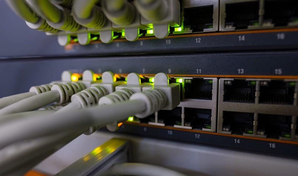
Unlike Layer 1 hubs, which transmitted all frames to all connected ports, switches exist at Layer 2 and carefully examine frames received by NICs, learning which physical port or ports on the switch to send frames to. The precise contents of the frame will vary, but Ethernet frames will comprise a header that contains the receiving machine’s physical MAC address, the transmitting machine’s physical MAC address, and the kind of protocol wrapped in the frame (most commonly IP or ARP). The actual data (ARP frame or IP packet) follows the header, followed by a trailer containing an error-detection technique, the frame check sequence (FCS), to ensure that no section of the data was altered unintentionally or maliciously during transmission.
The transmitting machine’s Data Link layer assembles outgoing frames and calculates the FCS by applying a standard mathematical procedure to the frame’s contents called cyclic redundancy check (CRC). The Ethernet trailer contains the CRC value. For incoming frames, the receiving machine does the identical computation, allowing it to validate the authenticity of the contents by comparing its locally produced FCS value to that supplied in the frame. The frame is dropped if the values do not match. Error repair and retransmissions are handled by the upper layers and protocols.
The Data Link layer also uses an access mechanism to determine how data is placed on the wire. All wired Ethernet networks used to employ the carrier sense multiple access/collision detection (CSMA/CD) wired access technique, but it is now automatically deactivated on switched full-duplex connections, which have been the standard for a long time. Wireless networks employ carrier-sense multiple access with collision avoidance (CSMA/CA).
There are two sublayers in the Data Link layer:
Control of Logical Links (LLC)
The LLC layer is in charge of flow control and error management, which were formerly handled by now-defunct protocols. When IP wasn’t the end-all-be-all protocol that it is today, it was also used to multiplex protocols. Only management protocols like as VTP (VLAN Trunking Protocol), CDP (Cisco Discovery Protocol), and STP use the 802.2 LLC header nowadays (Spanning Tree Protocol).
Control of access to the medium/media (MAC)
The physical address—that is, the MAC address burnt into the ROM chip of each NIC—is used by the MAC layer to address network devices. For both transmitting and receiving devices, this physical address is included in the Layer 2 header. The FCS is also added and verified by this layer.
ARP, CDP, Ethernet, STP, VTP, and 802.1Q are examples of Layer 2 protocols (VLANs).
Network (Layer 3) Layer 3 is the Network layer, which is in charge of routing and logical addressing. The Network layer IP addresses identify both the device and the network on which it is located. The network identity is used by routers to determine how to transmit packets to destination networks.
The Network layer splits the packet into smaller ones that will fit inside two or more frames if the data being transmitted is larger than the maximum transmission unit (MTU) permitted by the Layer 2 protocols (for Ethernet, it’s 1500 bytes). Fragmentation is the process of breaking up data into smaller bits at Layer 3.
Internet Protocol (IP), IP addresses, and routers are examples of Layer 3 components.
IPv4, IPv6, IGMP, and IPsec are all examples of Layer 3 protocols.
Layer 4: Transport Layer
For end-to-end communication, the sender application must select between connection-oriented TCP and connectionless UDP. Remove the IP addresses from an IP packet to show the Transport layer in operation. What’s left is a piece of data in a TCP segment or a UDP datagram, both of which have been covered previously.
TCP and UDP are two well-known protocols that operate at Layer 4.
Layer 5: Session Layer
The Session layer is in charge of initiating, maintaining, and terminating connections between programmes on communication devices, known as sessions. A socket is a combination of an IP address and a port that indicates a session for either side of a connection. This socket information is displayed using the netstat tool.
Layer 6: Presentation Layer
The Presentation layer used to be in charge of data conversion, such as compression and decompression, encryption and decryption, and formatting, but these tasks are now handled by other layers. This layer is the one that has the least to do with current communication.
Layer 7: Application Layer
The Application layer contains the network-related programme code and operations that execute on a computer system to either initiate (on the sending system) or serve (on the receiving system) the request (on the receiving system).
It’s important to note that the Application layer does not relate to programmes like Microsoft Outlook. It refers to the protocols or application programming interfaces (APIs) that those programmes use. Internet Message Access Protocol (IMAP) and Simple Mail Transfer Protocol (SMTP), for example, are key Application-layer protocols for e-mail, but they’re also used by a variety of end-user applications (such as Outlook and Mozilla Thunderbird).
DNS, DHCP, FTP, HTTP, HTTPS (SSL/TLS), IMAP, LDAP, SSH, and SNMP are examples of Layer 7 protocols.